
How to Use a Multimeter: Measuring Voltage and Resistance
Posted by Laura Harris on 4th Jun 2026
A multimeter is one of the most useful tools for troubleshooting issues on a circuit board. This guide will walk you through how to use it to measure two important values: voltage and resistance.
Measuring Voltage
Step 1: Attach Your Probes
Before taking any measurements, make sure your probes are inserted into the correct ports. Insert the red lead (positive) into the red port marked with a "V," and the black lead (negative) into the black port.
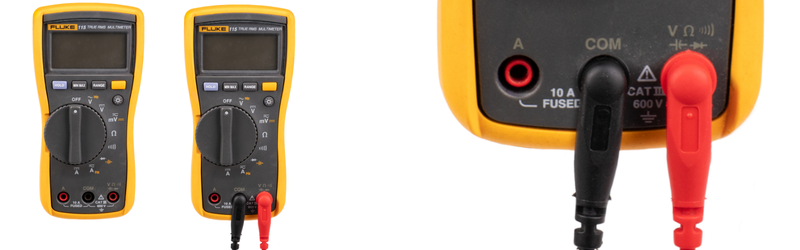
Turn the dial to the appropriate setting for what you're measuring. In this example we will measure DC voltage, but remember, whether you’re measuring AC or DC the procedure will be the same.
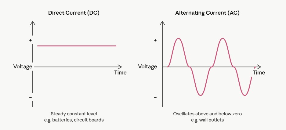
AC and DC Voltage
A multimeter can measure two types of voltage:
- AC voltage (alternating current): AC voltage periodically reverses direction and changes its magnitude over time. This voltage fluctuates in a wavelike pattern.
- DC voltage (direct current): Unlike AC voltage, DC voltage flows in a steady straight line. Direct Current is normal in batteries and small electronics like circuit boards.
Why are we measuring voltage?
Voltage tells us whether power is reaching the right parts of the circuit board and at the correct level. If a component isn't receiving the expected voltage, that's often a sign of a problem. This can be in the component itself or somewhere upstream in the circuit.
Step 2: Identify your measurement points.
Our support team will direct you to measure between two specific points. We'll call them Point A and Point B. These will be labeled or described in the instructions you receive. The below image shows an example of two points on a circuit board to test DC voltage.
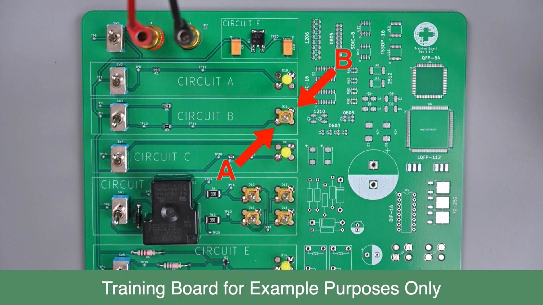
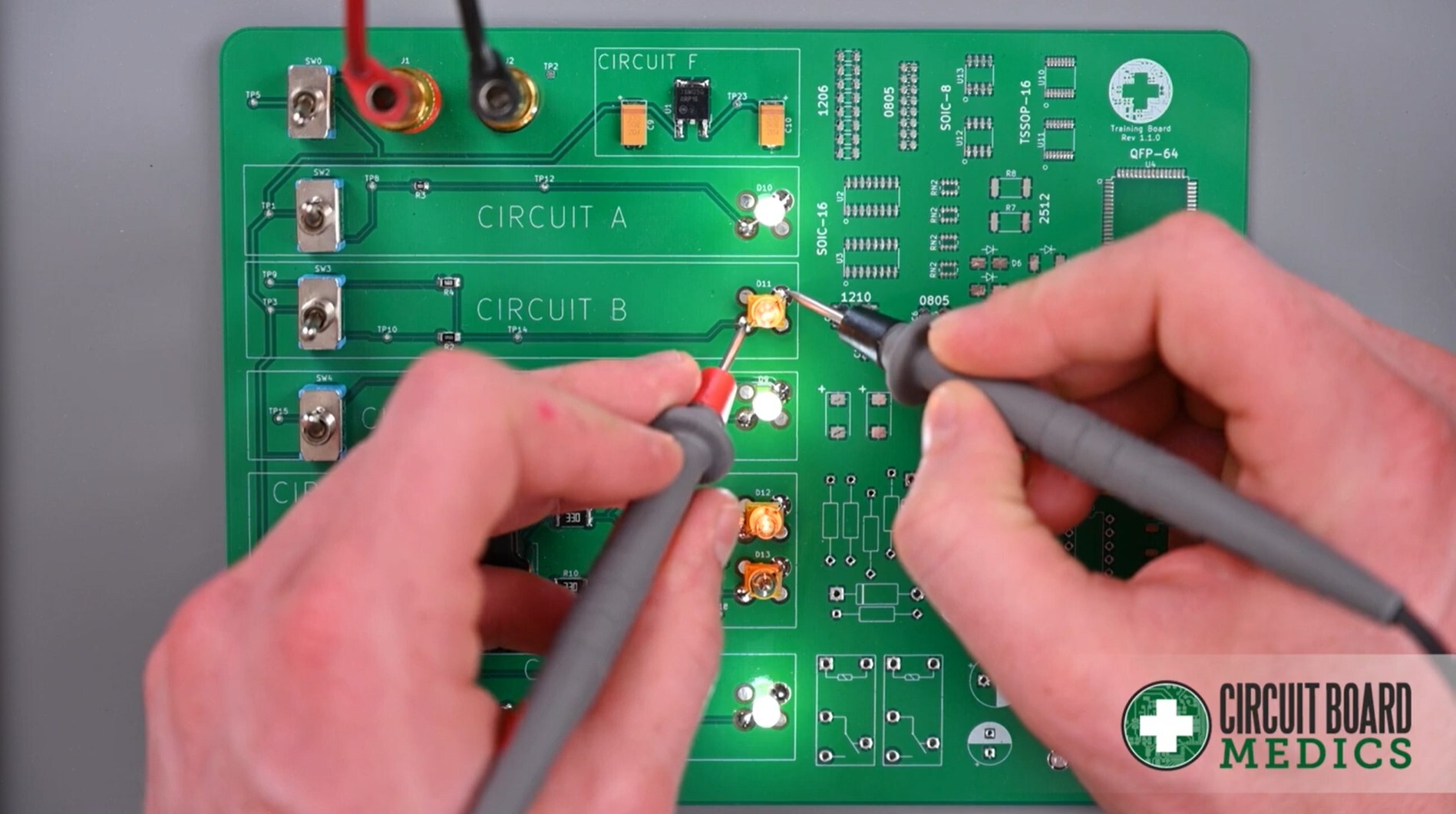
Touch the tip of one probe to Point A and the other probe tip to Point B.
Does it matter which probe goes where?
For DC voltage, yes. If you put the red probe on the negative point and the black probe on the positive point, you'll get a negative reading. This is not harmful to the meter, but it can cause confusion. When possible, place the red probe on the positive point and the black probe on the negative point (or ground). If you're unsure which is which, don't worry, just note the value regardless of sign and share it with our support team.
Note: if you are measuring AC and put the probes backwards you will not get a negative reading. Reversing the probes will not damage the multimeter or the circuit.
Step 3: Record the value
Read the number shown on the multimeter screen and write it down. Share this with our support team exactly as it appears, including any positive or negative sign. Our support team will compare your reading against the expected value for your specific board. A reading that's too high, too low, or zero where there should be voltage helps us pinpoint exactly what's going wrong.
Getting a Good Reading
A clean, firm connection between the probe tip and the measurement point is essential. Poor contact leads to inaccurate or unstable readings.
Make sure the measurement point is clean. Oxidation, flux residue, or debris on a solder pad can prevent good electrical contact. If needed, gently clean the point with a cotton swab.
Use adequate pressure, but not too much. You want firm, steady contact. You will need enough that the probe tip isn't slipping or bouncing. Think of it like pressing a pen firmly enough to write, not hard enough to tear the paper.
Measure Resistance
⚠️ Important: Power must be off before measuring resistance. Before placing your probes, turn off or disconnect power to the circuit board. Measuring resistance on a live circuit gives inaccurate readings and can damage your multimeter.
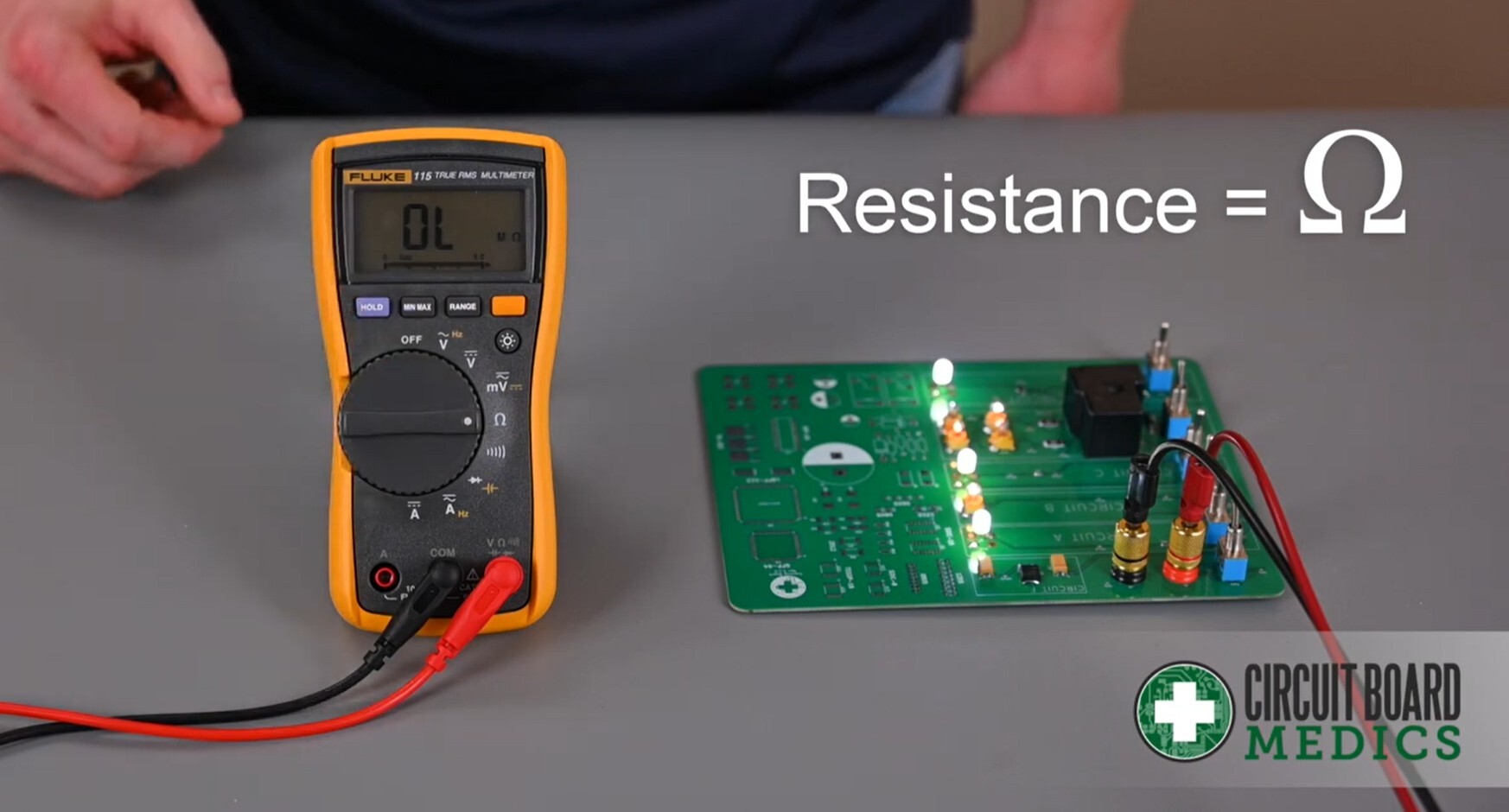
Switch the dial to the Resistance setting (marked with the Ω symbol). The process of placing the probes on Points A and B is the same as with voltage.
Step 1: Power off the board. Disconnect power completely before proceeding.
Step 2: Place the probes. Just like with voltage, place the probe tips on Points A and B as directed by our support team.
Step 3: Record the value. Write down the value shown on the screen, including the unit (Ω, kΩ, or MΩ). Share it with support and they'll let you know what it means for your specific situation.
Why measure resistance? Resistance tells us how much a component opposes the flow of current. Every component on a circuit board has an expected resistance value. If a resistor, coil, or other component reads significantly higher or lower than expected, or shows 0Ω (a short) or infinite resistance (an open circuit), that's a clear sign something is wrong.
That's it! Once you have these two measurements, voltage and resistance, you can send them to our support team so that we can help you with the next steps to fixing your module. When in doubt, follow the instructions provided by support and don't hesitate to reach out if a reading doesn't look right to you.